SteamVR Tracking License Day 2
Full Day
Alright! Today was our first full on training day, and we did nothing but learn from 9:00 – 5:00; it was so amazing! We’re all very much friends in the class at this point, cracking jokes and sharing ideas. Synapse does a great job at creating a fantastic educational environment; I’d be eager to return here in the future if I ever have the opportunity.
Highlights for the second day are that we learned how to simulate and optimize sensor placement, and we’re all getting pretty good at knowing what to look out for when designing tracked objects so they are sure to have the best tracking. Designing for lighthouse is very much a skill that comes with practice, and over time you develop an intuition for what will work best.
Simulation
So before diving into any physical hardware, Valve has created a magnificent visualization tool called HMD Designer. It’s got a few different options, but ultimately you feed it a 3D .STL model and it will spit out possible optimized sensor positions and angles for the best quality of tracking. Another thing you can do is feed it a .JSON file with the sensor positions already defined, but we’ll get into that later.
A great and key feature of HMD Designer is that it outputs multiple visualizations, primarily used to see how the lighthouse protocols interact with your object and its current sensor positions. FYI, dense lighthouse science ahead.
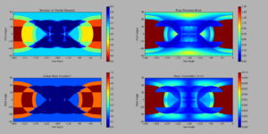
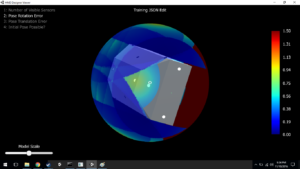
In this graphic (click to zoom), a 2D representation of how simulated tracking performs with your specific object helps tell us where any potential shortcomings of the current design may be. The bluer, the better! Also, regarding the format of these graphs, we are looking at unwrapped 3D visualizations (we’ll see the wrapped versions later). The left and right outer edges are -Z, centre is +Z, top is +Y, bottom -Y, and central-left is -X, central-right +X. If that doesn’t make sense, bear with me until the end of this section.
In the first graph, we see how many sensors can see the lighthouse at any given surface point of the object. The more sensors visible, the more datapoints we get! This is great because with more datapoints comes redundancy, and that really helps lock down a very definite pose.
In the second graph, we’ve got a heatmap of potential rotation errors. These errors are caused by all visible sensors residing on a very similar plane (discussed briefly in Day 1), and because of that, SteamVR will have a very tough time negotiating minute changes of rotations which face the lighthouse, as such rotations will frequently make very little difference to the time between contacting the lighthouse scan. Solving this problem can be done through adding / modifying sensors to be out of the plane created by other visible sensors.
For the third visualization, the simulation tells us if acquiring an initial pose is possible from various positions. An initial pose is acquired fully through the IR sensors – you can’t use an IMU for tracking if you don’t know where object was previously. Because of this, you need at least four sensors visible from a position, one removed from the plane of the other three (again, as you’ll notice, this fact is very important and more or less is the core of sensor placement design).
And finally, pose translation error rises from sensors being strictly colinear. First of all, if your sensors are colinear, you’re going to run into more problems than just pose translation error – namely rotation error since if the sensors don’t even have a plane, you certainly won’t have any sensors removed from one. Then either of those errors result in a failure to capture an initial pose. Secondly, if your sensors are colinear and are struck by the laser at specific times, then SteamVR has no way of understanding the rotation and position from these colinear sensors alone. There are a lot of possible positions in which the problem sensors would be struck at those times! Fixing this is simply pulling a sensor out of line (and hopefully out of plane as to avoid rotation errors).
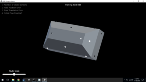
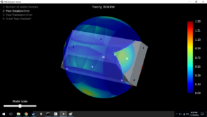
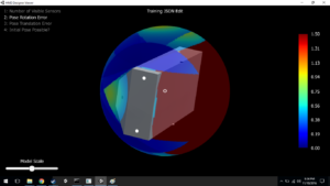
Then these images show Valve’s 3D visualization software that wraps the 2D graphs shown above onto a visualization sphere surrounding the object being simulated (in this example the object is a sort of beveled block). In the second 3D visualization, I have enabled rendering of the pose rotation error, which means that from the user’s point of view (which is the point of view of the lighthouse), pitch and yaw have potential to be uncertain in areas with more red. It comes without surprise that the rear of this object has complete failure to capture or estimate rotation, seeing as there are no sensors on that face! If you look at the perspective where that yellow cusp is within the reticle, in the third 3D viz capture, you can identify that most sensors in view reside on a plane that is normal to the perspective. If it weren’t for that fourth sensor inside the cusp, that area would be as red as the underside of the object is!
JSON
So all this information is great and valuable, but it doesn’t mean much to a computer as a bunch of colourful graphics. That’s where the JSON comes in. The JSON file is host to all important information unique to the device. Sensor positions, IDs, normals, IMU placement, render model, and a few other less important identifiers are all included in this magical file. The JSON is stored on the device, and is then presented to SteamVR when initially plugged in. Using the information contained within the JSON, SteamVR now knows how to interpret all incoming signal data from the device, and that means we’ve got sub-millimeter tracking in VR! (cough after calibration cough)
Optics
After all that high-level optimization and reporting, we got a brief rundown of optics and the challenges that come with protecting infra-red sensors for consumer use. Valve and Synapse have conducted a number of scientific analyses of how IR light interacts with different types of materials in different situations, and how those interactions effect sensor accuracy when receiving lighthouse scans. Comparing elements such as transparent vs. diffuse materials, sensor distance from cover, apertures, and chamfers, Valve and Synapse have come to the conclusion that a thin, diffuse material that is opaque to visible light but diffuse to IR is best for lighthouse reception. Additionally, an aperture is added around the diffuse material so that the light doesn’t activate the sensor before it should actually be “hit.”
Hardware!
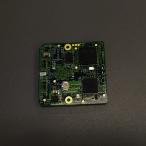
Then came the boxes. The glorious, unmarked cardboard boxes! We got a lot of goodies inside (I’ll be sharing my development with them over the next few weeks), but the most impressive tool is pictured below (thanks to Michael McClenaghan for the photography):
This is the Watchman board! On this little thing – only about a square inch – is just about everything needed to have a fully functioning SteamVR tracked device. The components it requires a (very easy) connection to are a battery, an antenna, a USB port, and of course the IR sensors.
Other fun hardware treats we received were IR sensor suite “chicklets,” which contain an IR sensor, Triad Semiconductor’s TS3633 ASIC, and a small handful of discrete components, some breakout/evaluation boards, input devices (including a trackpad identical to those included in Vive and Steam Controllers!), and some assorted ribbon cables. Oh, and of course – the reference objects!
Experimentation
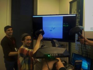
Synapse was kind enough to give us premade reference objects (which are really dense, by the way. One of the file names associated with it is “thors_hammer” and it is certainly worthy of such a name). These objects can be used as digital input devices, or if the handles are disconnected, they are large enough to fit over most modern-sized HMD’s for easy SteamVR Tracking integration! Photoed below is a group of us testing out our reference objects.
One of my favourite things about this image is how many controllers are connected in the SteamVR status window. Also, if you don’t know who I am, I’m the lad wearing the rainbow shirt. Hi!
Another reason we’re flailing our controllers around is to calibrate the sensor positions. When you prepare your files on a computer, all the sensors are in ideal locations. This, of course, is not how the real world works. So, through the magic of Valve UI, by flailing these unwieldy devices around for a minute or two, the sensors get a pretty good idea of where they are all actually located. We then take these corrected positions and write a new JSON file to the controller via the lighthouse console (this console is the bread and butter of interfacing with your tracked objects – you can extract firmware, stream IMU data, enter calibration, etc).
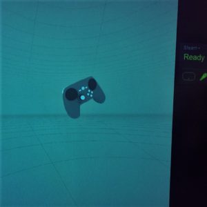
Fooling around a bit more, I decided to alter the JSON file on my reference object so it would be identified as a Steam Controller. And lo and behold! A Steam Controller in the SteamVR white room! Positionally tracked in all its glory.
And then to close the night, Synapse hosted a Happy Hour for us all to be social and inevitably geek out about VR together. We chatted about hardware, locomotion, multiplayer, narrative… I love this industry.
As usual, please feel free to post to the comments or email me at blog@talariavr.com with any questions or conversation. Be on the lookout for my summary post where I will answer community questions in bulk once the training is done. Cheers!
Hi Peter,
Thanks for continuing this great account!
You mentioned the sensors have an aperture, does that just mean they’re inset from the surface?
Mark, The aperture I refer to is best understood if you look at a Vive controller or HMD – in the dimples where all of the sensors at set in, the flat sensor bottom of the dimple is actually a separate material from the outer plastic. The aperture then is the hole in the outer plastic, which ends up exposing the diffuse transparent cover to the IR sensor. The inset of sensors from the surface that you see on official Vive products is a design choice made by Valve, somewhat due to the structure of older iterations. It’s not needed… Read more »
Makes sense, something else I could do with clarification on is how it can tell what lighthouse is hitting it? Since I would imagine the lasers from each station would hit at a different time? And can licensees buy more watchman boards?
Good question – the sync pulses vary in length depending on the setting of the basestation (eg. b channel will hold its pulse for x microseconds, while c channel will pulse for y). The tracked object simply waits for the pulse, and figures out which basestation is sending it based on the length. Then the basestation pulses / scans are staggered as to not step on one anothers’ signals. Licensees have access to schematics and gerber files and are free to fabricate their own Watchman boards, or variations of them. Synapse does not distribute Watchmans outside of the initial hardware… Read more »
Makes sense again, because the motors were always spinning I assumed they were also always pulsing but it makes sense to turn off the light for a spin.
Last question (maybe!), if I wasn’t bothered about rotation and just wanted to track something’s position, could I do it with 1 sensor? not worrying about occlusion
1 sensor would only give you your x and y position. Without at least 3 non-colinear sensors, you cannot determine the z position (depth). This is due to the “baseline,” as with 1 or even 2 sensors, the distance those sensors are from the basestation is ambiguous because if the 2 sensors were hit at time x and time y, then that could mean they’re at a very near depth to the basestation and tilted, or very far away and facing completely normal to the lighthouse (or anywhere in between). 3 sensors gives you that extra-dimensional reference of scale, so… Read more »
That’s really excellent! Does this still work?
That would depend on what you mean by “this” :) The hardware, simulations, and render model changes still work after the course.